Increased friction saves costs and weight
New Aerovide wind power plant
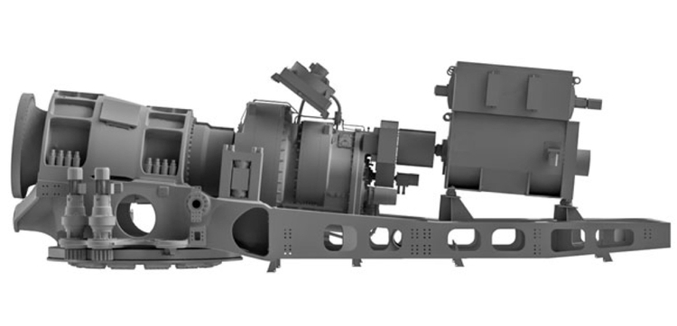
There’s a trend towards using larger facilities in both onshore and offshore plants, because these come with lower energy costs per kilowatt hour. Correspondingly, it also means that they’re more cost-effective to operate. The limitations are ultimately determined by the infrastructure of the respective country and the cranes available for erecting the turbines, particularly in the case of onshore plants.
Aerovide Energiesysteme GmbH, former "aerodyn", a wind turbine development company in Rendsburg, Germany, is currently inundated with requests for new facilities in the 4 MW class. With rotor diameters of 126 meters, 140 meters and 150 meters, this is currently the largest onshore class in development at Aerovide. Constructing systems of these dimensions poses a variety of challenges. There are weight limits for transporting the nacelle as well as restrictions on dimensions, with the height usually limited to the standard bridge clearance height of 4.20 meters.
As Technical Manager at Aerovide, Peter Krämer is responsible for bringing together all the in-house developments and coordinating the various specialist areas. Having headed the machine design department until recently, he’s fully aware of the objectives:
As a rule, designers and developers try to keep the loads as low as possible, yet at the same time streamline the structural components to the greatest possible extent in several loops.
Peter Krämer
“But this is of course to a certain degree also limited by the manufacturing process. For example, the wall thicknesses of the cast components may not fall below certain values,” he explains. “With our aeroMaster 4 systems, the objective is to maintain a transport weight of 75 tons per transport unit”.
Saving weight through measures to increase friction
Another focal point is optimising the bolt connections, the dimensions of which are dependent on the prevailing forces. The determining factor for dimensioning is often the high torques that are introduced by the rotor and then transmitted via the drivetrain and various other points – from the hub into the shaft, then into the gear unit and finally into the generator. “Flanges or bolt interfaces are required everywhere here, with high torques being transmitted through them. And it’s precisely at these points that you can ultimately introduce weight savings by increasing the coefficient of friction at the interfaces,” said Krämer.
There are various measures you can use to increase friction, such as zinc thermal spraying, a special application of paint or inserting friction foils from 3M. With this in mind, Aerovide tested various approaches in design and construction to effect weight savings in a newly developed 4 MW system. One area of focus was the connection point between the shaft and the gear unit.
Weight savings through extensive developmental steps
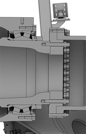
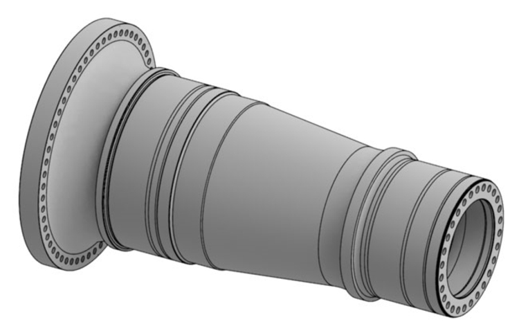
A comparison was made between a frequently encountered standard design that has a forged shaft with a clamping set for the gear unit – such as in the smaller aeroMaster systems of up to 2.5 MW – and the aeroMaster5 design, which has a cast-iron shaft and a flange for the gear unit instead of a clamping set. The choice fell on the cast-iron shaft with a relatively large diameter, since this saves the costs for the clamping set and also ensures easier dismantling for gear unit repairs.
Based on the experience gained in the development of the 5 MW-system, a solution that combined a spacer ring and a locking disk was selected.
The spacer ring has the advantage that it provides a large flange diameter for the gear unit and that the ring can also be used to hold the locking disk. In order to transmit the high torques, there must be a double-row screw flange on the shaft. There must also be access to perform maintenance on the screws – in other words, the diameter of the passage inside the shaft must not be too small and the cavity in the area of the gear unit flange should be correspondingly large. In the next stage of development, it was decided to bring the locking disk forward to the hub in order to make the nacelle transport unit lighter.
However, the advantage of the locking disk and spacer ring combination was then lost, so the focus turned toward finding a smaller, lighter solution that would incorporate a positive connection or measures to increase friction.
After extensive investigations, 3M Friction Shims were chosen as the solution.
The objective was to leave out the spacer and attach the connecting flange to the gear unit with a series of bolts. Foils to increase friction – 3M Friction Shims – introduce a variety of options for lighter and more compact constructions without having to compromise on power and torque transmission.
“The functionality of the 3M friction foils or 3M Friction Shims is based on diamond particles of a defined size and distribution that protrude from a chemical nickel coating. The coating is applied to thin steel foils which are punched or laser cut according to the customer's geometry. When the components are assembled, the diamonds then press into the surfaces of the counterpart component and thereby create a micro-positive lock”, is how Florian Grimm, global product manager for friction solutions at 3M, explains the operating principle. “With this method, static friction values of 0.6 and higher can be achieved. This means that depending on the application parameters, up to 4 times higher torques can be transmitted safely and reproducibly through the connection.”.
New design translates into many advantages in weight and cost
The new system was complex to develop – but it paid off. By eliminating the second row of screw connections, the designers were able to reduce the weight of the rotor shaft by around 200 kg. Leaving out the spacer reduces the weight by about 2 tons and translates into an estimated cost saving of around 5,000 euros.
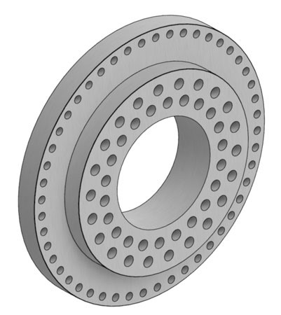
The smaller flange on the gear unit with a smaller shaft results in weight savings of 1 ton. The costs of the gear unit remain almost unchanged, because although the material for the planetary carrier with shaft is of higher quality and therefore more expensive, the size of the outer planetary carrier bearing could be reduced. Another advantage of the new design is that the number of bolts could be reduced – from 44 M56 studs to 28 M56 studs. And finally, the reduced number of bolts and better accessibility means shorter assembly times. The same applies to the maintenance of the bolts. This is also an important aspect, because all the important bolt connections must be checked on a regular basis.
Manufacturer expertise is crucial when it comes to foils for increasing friction
Peter Krämer knows that in a construction as complex as a wind turbine, it’s critical that the friction shims are designed with precision – and this requires a high level of expertise from the manufacturer. Florian Grimm describes how 3M approached this project: “First of all, the flatness and the roughness parameters of the counterpart components to be joined were determined. The corresponding 3M Friction Shim – in this case, grade 25 – was then selected based on these values. Subsequently, a drawing was made of the joining surface and divided into segments to facilitate manufacture, shipping and assembly of the 3M Friction Shims.”
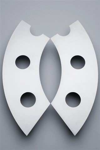
They expect to achieve a friction coefficient of >0.5 with the 3M Friction Shims. This was proven by Aerovide in extensive tests. The company works in collaboration with 3M and the Chemnitz University of Technology. “We have to demonstrate the specified coefficient of friction to the certification body,” explains Krämer.
The development process was ultimately just as complex as the tests. Working together, Aerovide and 3M developed a point-by-point weight- and cost-optimised plant design. In summary, the result translates into total weight savings of approx. 3.2 t and cost savings of several thousand euros.
Construction started in early 2016 and was completed in early 2018. The first plant was then built in Korea at the end of 2018. Another licensee from the Middle East has also begun series production of the system with the first plant opened in 2019.


